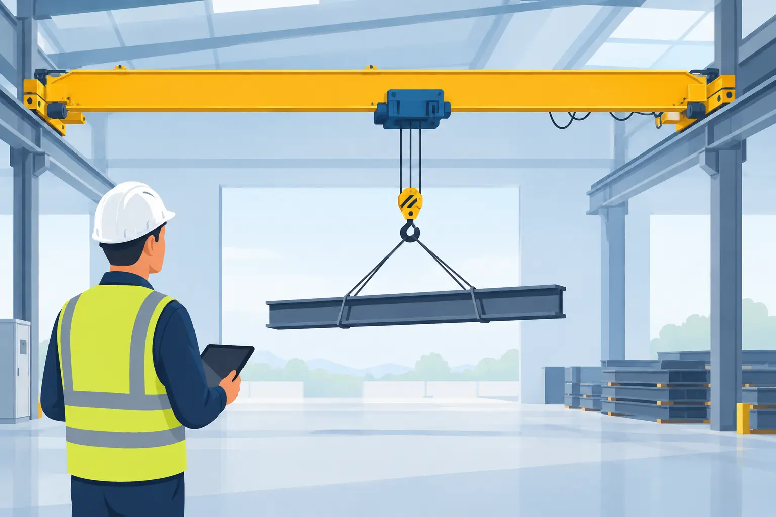
How to Calculate Overhead Crane Hook Height
Learn how to calculate overhead crane hook height, assess headroom and travel limits, and specify a lifting system that protects production and compliance.
CraneCert · 16 October 2026

A crane can have the right safe working load and still be the wrong crane for the job. If the hook will not lift a tool, fixture or fabricated assembly high enough to clear an obstruction, production stops or people are pushed towards unsafe workarounds. To calculate overhead crane hook height properly, start with the lift you need to complete, not simply the building height shown on an old drawing.
Hook height affects crane selection, runway design, hoist choice and the practicality of every lift beneath the system. It should be confirmed before ordering a new crane, changing a process, introducing larger tooling or moving a crane to another bay.
What overhead crane hook height actually means
Hook height is normally the vertical distance between finished floor level and the hook saddle, or the lowest practical point of the hook, when the hoist is in its highest working position. It is also often called height of lift or under-hook height. These terms are sometimes used loosely, so agree the measurement datum before comparing quotations or drawings.
For an existing crane, the useful question is: how high can the hook safely travel in reality, with the block, hook and lifting accessories accounted for? For a new installation, the question is: what hook height is required to perform the highest planned lift with adequate clearance?
Do not confuse hook height with building height. Roof trusses, lights, ducts, sprinklers, crane runway beams, electrification and the crane's own steelwork all reduce the space available. A high roof does not automatically provide high lifting capability.
Calculate overhead crane hook height from the lift requirement
The most reliable method works upwards from the load. First establish the minimum elevation the bottom of the load must reach to clear the highest obstruction on its planned travel path. Then add the dimensions from the bottom of the load to the hook.
A practical calculation is:
Required hook height = obstacle height + operating clearance + load height to lifting point + effective rigging height
The obstacle height is measured from finished floor level to the top of the item the load must clear. Operating clearance is the deliberate gap above it. The load height to lifting point is the distance from the underside of the raised load to its lifting lugs, trunnions or other attachment point. Effective rigging height is the loaded vertical distance from that point to the crane hook.
For example, a fabricated unit must pass over a 4.20 m machine enclosure. A 300 mm operating clearance is required, putting the underside of the load at 4.50 m. The distance from the underside of the unit to its lifting lugs is 950 mm, and the selected lifting arrangement adds 750 mm from lug to hook saddle. The required hook height is 6.20 m.
That figure is a starting requirement, not a crane specification. The available height must still be verified against the proposed crane and hoist arrangement.
Measure the rigging in its working condition
Rigging is frequently the missing dimension in early crane planning. Chain slings, wire-rope slings, spreader beams, lifting beams, plate clamps and below-hook devices can consume a significant amount of headroom. Their effective height changes with load geometry and sling angle.
A two-leg sling used at a shallow angle needs longer legs than one used closer to vertical. It may therefore require more height while also increasing leg tension. Where the load has a spreader beam or a dedicated lifting frame, measure the complete assembly under the intended connection arrangement. Do not estimate from a catalogue photograph or an unloaded sling laid on the floor.
If the load may be rotated, tipped or transferred onto a fixture, assess each stage separately. The maximum hook elevation is often required during the transfer rather than the main horizontal travel.
Establish the crane's available under-hook height
For a proposed crane, available hook height comes from the approved general arrangement drawing and the manufacturer's hoist data. It is determined by the elevation of the hoist running surface and the vertical space taken up by the crane girder, trolley, hoist body, rope reeving and hook block at its upper limit.
In simple terms:
Available hook height = hoist running level, hoist and hook-block construction depth
The precise dimensions differ substantially between crane types. A top-running single-girder crane, double-girder crane and underslung crane place the trolley and hoist in different positions relative to the runway. A double-girder arrangement can often provide better hook height for a given building, but that does not make it the automatic choice. Capacity, span, duty, building steel, access for maintenance and budget still matter.
Low-headroom wire-rope hoists and certain chain-hoist arrangements can recover valuable lifting height where the building is constrained. Equally, a low-headroom solution may involve trade-offs in capacity, speeds, maintenance access or initial project cost. The right option depends on the actual lift path and duty cycle, not the highest possible figure on paper.
Check the highest obstruction, not the obvious one
Survey the full crane travel area. The lowest obstruction could be a roof bracing member in one corner, a roller shutter track, an extraction duct, a lighting run or a future service installation. It may sit outside the normal production area but inside the route needed for maintenance, loading or occasional long products.
Where a crane bridges multiple bays, confirm changes in floor level and roof structure. Use finished floor level as the common datum and record every critical elevation. Laser measurement is useful, but it should be supported by a physical survey and checked against current building drawings where available.
Allow for real operating conditions
A calculation based on static dimensions alone can create a system with no usable margin. A load can swing, a rope can deflect, a crane structure can deflect under rated load, and the final hook position can be affected by limit-switch settings and component tolerances.
The clearance required is specific to the lift. A stable, guided load moving slowly over a fixed machine may need a different allowance from a long, awkward fabrication travelling across a busy bay. The assessment should consider load control, travel speeds, visibility, exclusion zones, the competence of the lifting team and whether the route is used repeatedly.
Do not assume there is one universal clearance figure written into LOLER. LOLER requires lifting operations to be properly planned, supervised and carried out safely by competent people. PUWER requires work equipment to be suitable and maintained. The practical clearance should therefore come from the risk assessment, the lifting plan and the equipment's documented operating limits.
For an existing crane, also verify the upper hoist limit. The limit must stop normal travel before the hook block contacts the hoist or drum arrangement. It is a protective control, not a target position to be used to gain an extra few centimetres of lift.
Common errors that lead to lost lift height
The most expensive errors are normally made before installation. Four issues appear repeatedly:
- Measuring to the roof rather than the lowest item in the lift route.
- Omitting the height of a spreader beam, lifting frame or angled sling arrangement.
- Comparing crane quotations without confirming whether each supplier states hook height from the same datum.
- Treating the upper limit as normal working travel rather than allowing a safe operational margin.
Another common problem is specifying a crane around the current product but not the next one. If a facility expects taller fabrications, new machining centres or different handling fixtures, those plans should be tested while the crane design is still flexible. Altering runway height or replacing a hoist after installation is usually far more disruptive than allowing for the requirement at project stage.
Record the calculation for compliance and future changes
The calculation should form part of the crane project file and the lifting-operation planning record. Keep the surveyed elevations, load drawings, lifting-accessory details, selected hook height, crane general arrangement drawing and any assumptions about clearance or travel route together.
This provides a clear basis for handover, operator instruction, maintenance planning and future LOLER thorough examination records. It also helps when a production manager asks whether a new fixture can be introduced safely. Instead of relying on memory, the decision can be checked against an auditable set of dimensions.
For ageing equipment, a site survey may show that a replacement hoist, revised lifting beam or crane upgrade is enough to solve the height problem. In other cases, the constraint lies in the building or runway, and a new crane configuration is the more commercially sensible answer.
Before committing to equipment, walk the intended load through its complete route on paper and on site. The critical dimension is not the hook height listed on a quotation, it is the safe, repeatable clearance your operation has when the real load, real rigging and real building are all involved.